Milk cooling
Topics
8 min read
Milk cooling is the process of lowering the temperature of milk after milking to maintain its quality. The page explains the importance of selecting the right cooling system for your farm, which can lead to lower energy costs and less risk of penalties due to milk temperature. It provides detailed guidance on New Zealand's milk cooling standards that must be adhered to, various methods of cooling including Plate Heat Exchangers and Vat refrigeration, and options for further cooling like cooling towers, ice banks, and snap chillers. The page also gives instructions on checking and improving the performance of your cooling system.
Raw milk grows bacteria rapidly above 7°C. Meeting the new milk cooling standards, which came into effect for all farms on 1 June 2018, may mean changes are required for your system.
The Ministry for Primary Industries New Zealand Code of Practice for the design and operation of Farm Dairies has new milk cooling standards.
The rules apply to:
The rules state that raw milk must:
In situations where there is continuous or extended milking, such as automated milking systems, the milk must enter the bulk milk tank at 6°C or below. “Continuous or extended milking” is defined as milking for six hours or longer from the time that milk first enters any bulk milk tank.
Check the performance of your current plate heat exchanger. See 'checking the performance of the plate cooler' further down the page.
Consult with your milk company to determine if your current system will meet the new milk chilling requirements.
Download: New Zealand Code of Practice for the design and operation of Farm Dairies.
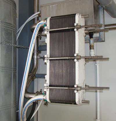
Plate Heat Exchangers (PHE) are the most cost-effective way to cool milk.
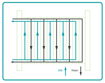
A PHE consists of a series of very thin stainless steel plates. Water flows along one side of each plate while milk flows along the other. Heat is transferred from the milk to the water via the plate. The capacity of a plate cooler is adjusted by adding or subtracting plates.
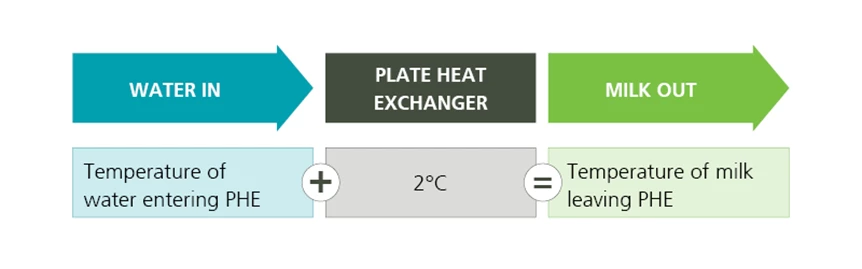
The easiest way to check the effectiveness of your plate cooler is to compare the temperature difference between the incoming temperature of the cooling water and the outgoing temperature of the milk leaving the plate cooler.
An efficient PHE should cool milk to within 2°C of the water before it enters the PHE. For example, if the temperature of the incoming cooling water is 14°C, the temperature of the milk exiting the plate cooler should be about 16°C.
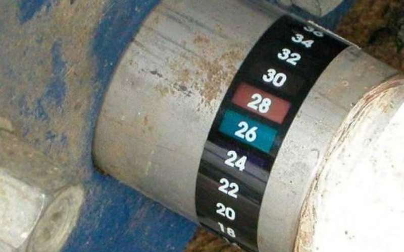
One simple way to check this is to use a PVC strip thermometer. These thermometers have a paper backing on them, which is peeled off and stuck directly onto a clean, dry metal pipe.
How to use a PVC strip thermometer
Note: Improving the efficiency of plate cooling is likely to require the services of a skilled technician. Cleaning the plates is not an easy task – it is time consuming and best left to experts. Inefficient systems may need resizing, extra pumping capacity, additional cooled water storage or a complete dismantle and service. The additional capital and service costs should be considered against the annual costs of using an inefficient plate cooler. The cost of an inefficient plate cooler increases in proportion to the annual milk production of the farm.
The peak flow rate of milk expected from the milk pump will determine the type of pre-cooler (size of the plates) and number of plates required.
Ideally plate coolers should use the coldest available water on the farm. Some fluctuation in temperature can be expected over the year, but this is still an inexpensive way on most farms to initially reduce the temperature of milk from around 35°C to <18°C, and will significantly reduce the load on the refrigeration system.
The ‘M-series’ plate coolers are the most common type found in New Zealand dairies and are available in 'single' bank and 'double' bank configurations. The ‘M-series’ is designed to handle milk flow rates of up to 4,500 litres per hour.
Industrial plate coolers are more suitable in situations where milk flow rates exceed 4,500 litres per hour. Industrial plate coolers are much bigger in size than the ‘M-series’ and are designed for flow rates up to 12,000 litres per hour.
In refrigerated/direct expansion tanks the refrigerant is pumped into the jackets (evaporators commonly referred to as ‘dimple plates’) on the internal surfaces of the bulk milk tank.
Here the refrigerant expands as it takes heat from the milk, is pumped out of the jackets, compressed, then pushed into the condenser. The hot refrigerant is cooled by air (or water) flowing through the condenser fins. The cooled gas condenses into a liquid and is pumped back in to the jackets around the bulk milk tank to start the cycle again.
Direct expansion has the disadvantage of maximum power draw during and after milking which is generally peak rate. If large electric motors are used there can be problems in areas of poor power supply.
Direct expansion refrigeration systems are pressurised, which means they require a skilled technician for maintenance.
If your current plate heat exchanger and refrigeration unit combination are not capable of meeting the new milk cooling regulations you may need to consider a secondary cooling option. These can involve a large capital outlay and long payback period but may come with the benefit of heat recovery, enabling you to save on hot water costs. Carefully evaluate all options to ensure the system is fit for purpose without over capitalising.
Cooling towers
Cooling towers can be very effective at cooling water especially in areas of low humidity. Water can be cooled to within 5°C of the wet bulb temperature in a properly designed plant.
The most effective plants are fan forced and turn over a large store of water every hour. They operate overnight to cool a large volume of water, usually 4½ times the volume of the daily milk yield.
Ice banks
Ice banks generate ice along evaporator coils using night-rate power. The ice is used to chill water for the pre-cooler. The warm water is then returned from the pre-cooler to the top of the ice bank and cooled again as it runs down the ice.
These systems can require more maintenance than other systems and are not as energy efficient as a direct expansion vat. If working on night rate electricity rates they may save money even though they use more energy. Ice banks take up less space than storage of chilled water.
Snap chillers
Another option is to use a refrigeration system to cool water or a food grade glycol/water mixture. Glycol systems tend to use a very small volume of fluid and create the chilled fluid on demand (at milking time).
Note that a system that is designed to chill milk to 4°C in line i.e. prior to vat entry, will need a much larger (and more costly) compressor than an in-vat system. Generally, these systems are a big capital expense.
Thermal stores
Thermal storage systems chill water using off peak power and require an insulated storage tank to hold a large (one day’s milking) volume of chilled water. Using more energy than a direct expansion tank they have advantages relating to installation and maintenance procedures.
Vat wraps
Vat wraps are only utilised by 20% of dairy farms in New Zealand but can save around 15-25% of milk cooling costs. They insulate your milk from outside temperatures and weather, preventing it from heating up and reducing energy used by the refrigeration unit.
Effectiveness of a vat wrap will depend on whether your vat is inside or outside and where in New Zealand you are located.
Estimate savings from vat wrap installation and payback using the Energy Efficiency and Conservation Authority (EECA) calculator.
Now’s the perfect time to check in, plan, and set up for a strong season. We’ve pulled together smart tips and tools to help you stay ahead all winter long.
Whether you prefer to read, listen, or download handy guides, we’ve got you covered with trusted tools to support your journey every step of the way.
Put our proven strategies and seasonal tools to work. Boost production, support animal health and watch your profits hum.
Tools that are backed by science, shaped by farmers and made for this season.
That’s Summer Smarts.
Autumn Smarts brings together the research-backed tools that build resilience and boost performance.
The tools and insights you need to navigate the season with confidence. Backed by research and built for results – that’s Winter Smarts.


